Code-3 21TR & 21TR Plus Manual do Utilizador Página 1
Consulte online ou descarregue Manual do Utilizador para Iluminação Code-3 21TR & 21TR Plus. Code 3 21TR & 21TR Plus User Manual Manual do Utilizador
- Página / 18
- Índice
- RESOLUÇÃO DE PROBLEMAS
- MARCADORES
- and 21TR Plus 1
- Introduction 2
- Installation & Mounting 3
- Permanent Mounting 4
- Wiring Instructions 5
- Fusing - 21TR 6
- Wiring - 21TR 6
- Diagnostic Test 6
- Level/Switch Energized 8
- Wire Color 8
- Pattern Description Notes 8
- Fusing - 21TR Plus 10
- Wiring - 21TR Plus 10
- WARNING! 10
- ArrowStik® Pattern Selection 12
- Take Down and Alley Lights 14
- Maintenance 16
- Troubleshooting 17
- PRODUCT RETURNS 18
- WARRANTY 18
Resumo do Conteúdo
1INSTALLATION& OPERATION MANUAL21TRTM AND 21TR PLUSTM LIGHTBARRead all instructions and warnings before installing and using.INSTALLER: This man
10Fusing - 21TR PlusTMThe light bar should be installed with an external fuse or circuit breaker in the RED lead of the 2 conductor 10 AWG power cable
11Notes: *When the ArrowStik® Left and ArrowStik Right wires are both connected to +power, the Center-Out ArrowStik function is activated.**When the P
12ArrowStik® Pattern SelectionThe 21TR Plus™ is designed to offer user selectable traffic directing signals and traffic warning options
13Steady Burn Setting - 21TR PlusTM The Steady Burn feature allows up to two (2) of the light bar's light heads to be designated to operate in St
14Take Down and Alley LightsAlley LightsLocated at the ends of the light bar to provide light to the side of the vehicle. Stationary Lamps/Takedown L
15Take Down and Alley Light Flash Mode - 21TR PlusTMThe Take Down and Alley Lights can be programmed to ash at different rates. Reference Table 6.
16MaintenanceLens CleaningUse plain water and a soft cloth, or Code 3® lens polish and a very soft paper towel or facial tissue. Because plastic scr
17 Parts List & Exploded View(Reference numbers identify items shown in Figure 11)Ref No. Description Part No. 1 Bottom Outboa
18WARRANTY Code 3®, Inc.’s emergency devices are tested and found to be operational at the time of manufacture. Provided they are installed and o
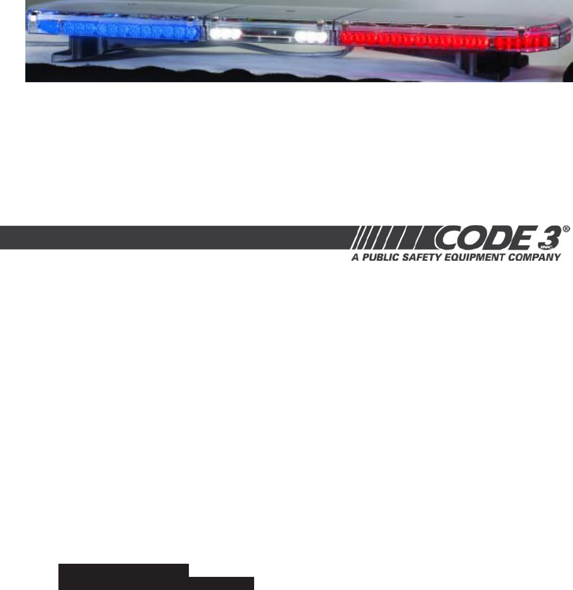
2IntroductionThe 21TR™ & 21TR PlusTM Light Bar is a light bar that is approximately 2" high, yet delivers unobstructed 360° warning and more
3Installation & MountingMounting HardwareAll mounting hardware is packed in a small box inside the main carton. Four standard kits are available:
4Mounting Bracket5/16-18 Carriage BoltCustomer Supplied BoltPlastic Shim (if needed)Rubber Foot5/16" NutFIGURE 3Bottom of LightbarNOTE: Tighten o
5Wiring InstructionsBefore attempting to connect wiring refer to wire tag attached to the lightbar's main cable. Each wire in the cable controls
6Fusing - 21TRTMThe light bar should be installed with an external fuse or circuit breaker in the RED lead of the 11 conductor cable. The recommended
7Factory Defaults - Flash PatternsFind below the seven default ash patterns for the various combinations of wires. Reference Table 2 for all ash p
8Progressive vs. Independent SwitchingIn a 3-level progressive switch application there are only 3 patterns that typically need to be set.Example 1:
9Setting Flash PatternsStep 1Power-up the light bar by connecting the Red wire to +12V and the Black wire to ground, and select Level 1 on a user-purc
Manuais e produtos relacionados com Iluminação Code-3 21TR & 21TR Plus
 (12 páginas)
(5 páginas)
(24 páginas)
(12 páginas)
(12 páginas)
(5 páginas)
(24 páginas)
© 2020, manymanuals-pt.com. Todos os direitos reservados. | 0.029 s |
 Manymanuals.com
 Manymanuals.de
 Manymanuals.fr
 Manymanuals.it
 Manymanuals.pl
 Manymanuals.cz
 Manymanuals.es
 Manymanuals-pt.com
Comentários a estes Manuais